Harmonic Reduction
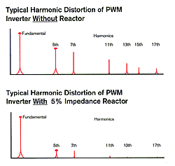
Because all standard MTE reactors are compensated for harmonics (current and frequency), they are extremely effective at reducing the amount of harmonics which are produced by a drive/inverter. Use 5% impedance, harmonic compensated reactors for the best single stage reduction of harmonic distortion. For the guaranteed harmonic mitigation see Matrix AP Filters.
| Percent Harmonics vs Total Line Impedance Total Input Impedance
|
 |
Reactor Linearity
 This curve illustrates the linearity of MTE reactors. Even at 150 percent of their current rating, these reactors still have 100% of their nominal inductance. This assures maximum filtering of distortion even in the presence of severe harmonics and best absorption of surges. The typical tolerance on rated inductance is plus-or-minus 5 percent.
You Benefit from These Unique Features
HARMONIC COMPENSATION makes MTE reactors suitable for use on either the drive input or drive output. They are designed to carry full rated fundamental current plus handle current and frequencies associated with harmonics up to 50 percent more.
TERMINALS are provided as standard to save installation cost and minimize panel space. Finger proof (IP20) terminals are provided through 45 amps, solid copper box lugs above that to 400 amps. Tab type terminals are available as an option.
EPOXY IMPREGNATION minimizes audible noise in the reactor and enhances structural integrity.
IGBT PROTECTION allows all MTE standard reactors to be used on the output of variable frequency drives including IGBT types with switching frequencies up to 20 KHZ. A premium dielectric system is utilized to protect the first, last and end turns from the potentially high circuit peak voltages and fast dv/dt which are experienced in applications with long leads between the inverter and motor. Additionally, the general dielectric system of each reactor meets UL-506 (4000 volts rms).
HIGH SATURATION CURRENT RATING of MTE reactors maximizes their surge current protection capability. MTE reactors absorb many of the power line disturbances which cause nuisance trips on voltage source inverters. 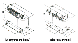
OUTLINE DIMENSIONS All MTE reactors are supplied with field wiring terminals, as illustrated. Units rated 45 amperes or below are supplied with the international terminal block as shown. Reactors rated above 45 amperes thru 400 amperes are supplied with solid copper box lugs. Larger reactors are supplied with copper tab type terminals. Refer to these outline drawings and the table on page 7 for reactor dimensions.
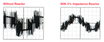
MOTOR PROTECTION Reactors provide a level of protection from the high peak voltages and fast reise times (dv/dt) which can be exsperienced in IGBT inverter applications when the distance between the inverter and the motor is long.Refer to MTE application guides to determine if a reacdtor will offer suitable protection in your application or whether you should consider a dV/dt or sine wave filter.
- For 1000 foot guaranteed protection see MTE DVDT Filters
- To supply a guaranteed 5% THVD sine wave at the motor terminals see MTE sine Wave Filters.
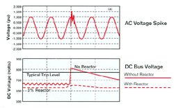 VOLTAGE SPIKE PROTECTION A 3% impedance reactor is very effective at protecting against damage to or nuisance tripping of AC voltage source inverters, due to voltage spikes.Voltage spikes on the AC power lines cause elevation of the DC Bus voltage which may cause the inverter to “trip-off” and indicate an over-voltage protection condition. Use reactors to absorb these line spikes and offer protection to the rectifiers and DC Bus capacitors while minimizing nuisance tripping of the inverter.
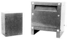
NEMA 1 CABINETS All MTE reactors are available as either open type or in a NEMA Type 1 general purpose enclosure. To order a reactor mounted in a cabinet simply change the second last digit of the part number from “0″ to “1″. Example RL-00802 becomes RL-00812.
|
Reactor Part Number
|
Type
|
H
|
W
|
D
|
WGT. (LBS)
|
Cabinet
|
|---|---|---|---|---|---|---|
| RL-002XX, RL-004XX, RL-008XX, RL-012XX, RL-01801, RL-01802 |
Wall Mount | 8 | 8 | 6 | 6 | CAB-8 |
| RL-01803, RL-025XX, RL-035XX, RL-045XX, RL-055XX, RL-080XX, RL-100XX, RL-130XX, RL-160XX, RL-200XX, RL-25001 |
Floor | 13 | 13 | 13 | 18 | CAB-13V |
| RL-25002, RL-25003, RL-320XX, RL-400XX, RL-500X1 |
Floor | 24 | 17 | 17 | 27 | CAB-17V |
| RL-500X2, RL-500X3, RL-600XX, RL-750XX |
Floor | 47 | 27 | 25 | 144 | CAB-26C |
| RL-850XX | Floor | 31 | 72 | 25 | 220 | CAB-26D |
